Acoustic Velocity System
The Acoustic Velocity System, a bench-top system designed to acquaint the student with the acoustic properties of reservoir rocks, complete laptop based data acquisition system for 1 inch diameter plug-size samples. The system determines wave velocities on rock samples as a function of confining stress and pore fluid pressure comprising a ultrasonic transducer assembly, pressure vessel (Core Holder) and pore pressure intensifier.
The custom built ultrasonic transducer assembly consists of a matched pair of transmit and receive transducers which can propagate a compression wave (P) or polarized shear wave (S) through a saturated (or partially saturated) rock sample. The core handling system includes a 5,000-psig hydrostatic core holder for 1 inch diameter samples with a confining pressure pump and a hydraulic operated pore pressure intensifier system.
The digital data acquisition system includes a laptop, XP Professional operating system, on-board data communication hardware, digital oscilloscope, pulser/receiver, spectrum analyzer and system control software.
Specifications:
HIGH PRESSURE CORE HOLDER ASSEMBLY is designed to ASME specifications for use with hydraulic confining fluids at confining pressures up to 5,000 psig. The data acquisition software monitors confining pressure. Two pore pressure ports allow “squeeze out” pore volume changes to be determined during pressurization of the sample and facilitate the changing of pore fluid during the experiment.
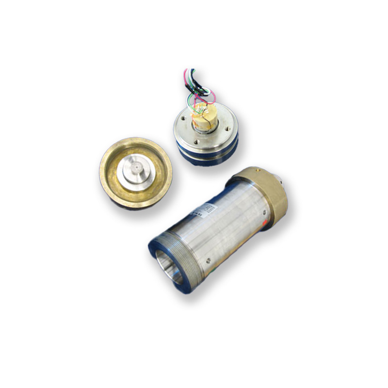
ULTRASONIC TRANSDUCER ASSEMBLY are provided for measuring the ultrasonic properties of 1 inch core samples at confining pressures up to 5,000 psig and pore pressures up to 4,500 psig. The ultrasonic transducer/sample assembly vertically inserts in to the core holder assembly. Pore fluid pressure is transferred to the jacketed sample through ports in the transducer assembly. The ultrasonic transducers are capable of sequentially propagating a compressional P-wave or shear S-wave signals down the axes of cylindrical samples with a center frequency of approximately 800kHz.
Compressional and shear wave velocities are calculated from travel times and sample length. The compressional and shear velocities may be combined with bulk density to calculate dynamic moduli, Young’s, bulk and shear, along with Poisson’s ratio. P and S wave signal selection, source excitation, and signal conditioning of the ultrasonic signal from the receiver are controlled by integrated pulser/receiver, digital oscilloscope, computer interface, and software combination described below.
LAPTOP WORKSTATION consists of a USB 2.0 ultrasonic pulser-receiver with software replicating a digital oscilloscope and digital signal processing and spectrum analysis. The pulser/receiver excites the source transducer with a high-voltage pulse and amplifies and filters the signals propagated to the receiver transducer. A digital oscilloscope board displays and digitizes the ultrasonic signals. An ultrasonic switch selects the compressional wave or either of the two shears wave signals. The data acquisition software also monitors and displays confining and pore fluid pressures.